Building the Ploopy Adept BLE (Any Ball Mod)

Disclosure: This post may contain affiliate links. If you make a purchase through these links, I may earn a small commission at no additional cost to you.
Introduction
If you love the Ploopy Adept but want to cut the cord, building the Ploopy Adept BLE is the ultimate upgrade. Taking it a step further with the Any Ball Mod (which is highly recommended) allows you to use standard 52.4mm billiard balls for an incredibly smooth, customized rolling experience.
This guide will walk you through the entire DIY process—from sourcing your parts and ordering the PCB, to soldering the components and getting your firmware running.
Parts List
Before heating up the soldering iron, make sure you have all the necessary components gathered:
- 3D Printed BLE Bottom: A modified housing designed to fit the battery, controller, and an on/off switch. Available in the AdeptBLE repository on GitHub.
- 3D Printed Any Ball Top: A modified top housing to accommodate the larger billiard ball. Available on GitHub.
- Any Ball: You can use a standard 52.4mm billiard ball. Here is an example.
- Bosch Rexroth BTUs (KU-B8-OFK): These ball transfer units provide that signature, frictionless glide. You can find them at Keycapsss.
- XIAO nRF52840 Board: The main microcontroller handling the Bluetooth connectivity. Buy one here.
- PMW3610 Optical Sensor: A highly efficient, low-power sensor perfect for battery-operated wireless devices. Source it from AliExpress.
- 3.7V Battery: Size is absolutely critical here! Your maximum compartment size is 47mm x 23mm x 8mm. This one for example fits.
- On/Off Switch: A standard 3-pin slide switch, like this one.
- D2LS-21: If JLCPCB is out of stock, grab these here and hand-solder them yourself.
Ordering the PCB from JLCPCB
Having your PCB manufactured and partially assembled by JLCPCB will save you a massive amount of time and effort. Follow these exact steps for a clean build:
- Upload Gerbers: Download the AdeptBLE files from the GitHub repo. Go to JLCPCB, click "Add Gerber File," and upload the
sensor.zipfile located inAdeptBLE -> electronics -> production. - Health & Safety: Leave most of the manufacturing defaults as they are, but change the Surface Finish to Lead Free HASL.
- PCB Assembly (PCBA): Toggle on "PCB Assembly." Choose a quantity of 2 or 5 (JLCPCB does not allow single-board orders). Having a backup board is highly recommended in case you make a mistake during the manual soldering phase later.
- BOM & CPL Files: When prompted, upload the following files from the
productionfolder:- BOM:
bom.csv - CPL (Positions):
positions.csv
- BOM:
- Handling Missing Parts: JLCPCB likely will not have the D2LS-21 mouse switches or the TCR2EF19,LM(CT regulator in stock (yes, that's the actual name). It’s perfectly fine to complete your order with these parts missing; they will solder the rest, and you can add the missing parts yourself later.
For reference, here are the parts that were successfully populated by JLCPCB during my order:
| Designator | Manufacturer Part # | JLCPCB Part # |
|---|---|---|
| C4 | YAGEO CC0603KRX7R9BB104 | C14663 |
| C1-C3, C6-C9 | Samsung Electro-Mechanics CL10A475KO8NNNC | C19666 |
| C5 | Samsung Electro-Mechanics CL10A105KB8NNNC | C15849 |
| U1 | TI TLV70018DDCR | C79924 |
| R1 | UNI-ROYAL 0603WAF2004T5E | C22976 |
| SW1-SW6 | OMRON D2LS-21 | C3823622 |
Assembly and Soldering
Once your partially assembled boards arrive, it's time to do some manual soldering.
You can use these pictures for your reference:
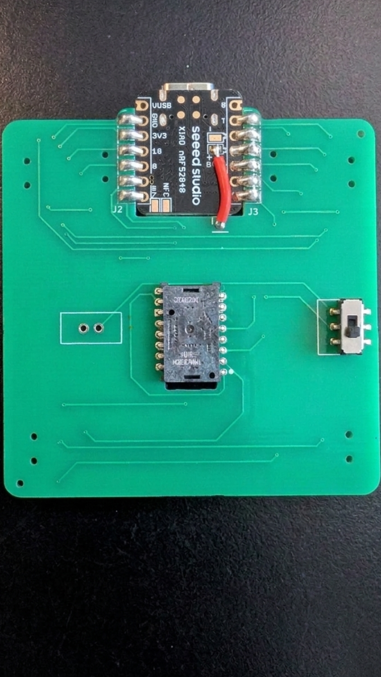
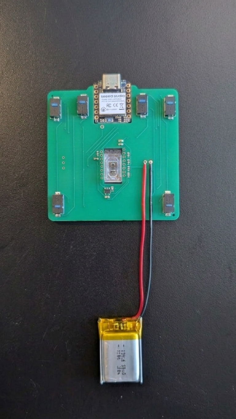
- Switches: If JLCPCB didn't have them in stock, solder the 6 Omron D2LS-21 mouse switches into place.
- The "Red Wire" Mod: Pay close attention to the small copper wire that needs to be soldered directly from the PCB onto the BAT+ pin of the XIAO.
- Sensor & Power: Carefully solder the XIAO microcontroller, the on/off switch, the battery leads, and the PMW3610 optical sensor to the board.
Firmware & Software
You have two main options for getting your trackball running:
- Pre-compiled Firmware: For the easiest route, download the ready-to-use
.uf2file directly from the AdeptBLE Repository. - Custom Build: If you want to customize your keymap, you can build your own firmware using the mouse-test repository. Important note: The current main branch may fail to build. Make sure to apply the fix found in Pull Request #3.
To Flash: Press the Reset button on your XIAO board twice rapidly to enter bootloader mode. It will mount to your computer as an external drive. Simply drag and drop the .uf2 file onto the drive.
Housing Assembly
You're in the final stretch!
- Prep the Shell: Assemble your 3D printed top and bottom housings, taking care not to pinch the battery wires.
- Install Bearings: Press-fit the Rexroth BTUs into their slots on the top housing.
- Drop the Ball: Insert your billiard ball, power it on, and enjoy your custom Ploopy Adept BLE Any Ball Mod!
Troubleshooting Checklist
If your trackball isn't rolling right away, run through these quick checks:
- Connectivity: Is the XIAO reachable via your PC when the reset button is double-pressed? (The reset button is located directly on the XIAO board).
- Wired vs. Wireless: Try plugging it in. Does it work via USB even if the Bluetooth connection is struggling?
- Button Check: Do all 6 buttons click physically and register inputs in your operating system?
- Sensor Height: The PMW3610 sensor is notoriously picky about focal length. It only detects movement at a very specific distance of 0.2cm - 0.5cm. Make sure your sensor is seated flush and your ball is at the correct height.
Read Next
Glove 80 - Per-Key Coloring
The Glove 80 is a mechanical keyboard with per-key RGB lighting. In this post we will explore how to set the colors of the keys.

Daily Bugle TryHackMe Write-Up
The Daily Bugle room on TryHackMe is a hard room that requires you to compromise a Joomla CMS account.

How to Access Raspberry Pi GPIO Pins Inside a Docker Container
Trying to control your Raspberry Pi's GPIO pins from inside a Docker container? Here is the quick solution using docker-compose and /dev/gpiomem.